
This article is a part 2 of a series of blogs about IFC authoring in a simple text editor.
Part 1 lays out the fundamentals of writing an IFC file. To follow along, you’re highly advised to have seen it. In the first blog we have defined a project, units used and a spacial hierarchy. In this part, we will be creating a physical element (a wall), to which we will assign a simple geometry.
Wall
To represent a wall, we can use the entity IfcWall
IFCWALL(GlobalId,?OwnerHistory,?Name,?Description,?ObjectType,?ObjectPlacement,?Representation,?Tag,?PredefinedType)
GlobalId: Unique global identifier := '0I8UD4qB9DjwVCwE644OEQ'
?OwnerHistory: May capture creator history and origin (application) := $
?Name: Short name := 'Wall'
?Description: Provides additional information about the entity := $
?ObjectType: Optional type := $
?ObjectPlacement: Placement of the element in space of type IfcLocalPlacement.
?Representation: Defines the geometry associated with an element of type IfcProductDefinitionShape.
?Tag : The tag (or label) identifier at the particular instance (occurrence) of a product, e.g. the serial number, or the position number.
?PredefinedType : Predefined generic type for a wall that is specified in the enumeration IfcWallTypeEnum.
To add the newly defined wall to our IFC model, we will append the file with the following line
/* WALL */#39=IFCWALL('0I8UD4qB9DjwVCwE644OEQ',$,'Wall',$,$,$,$,$,$);
Most of the optional attributes are left undefined, i.e $ for reading and comprehension simplicity purposes.
So far, the IfcWall entity has been created, but it is yet to be associated with a 3D geometry (i.e. ?Representation) or a position in 3D space (?ObjectPlacement)
Spatial containment
To place a physical element within the spatial structure of our project, we use the entity IfcRelContainedInSpatialStructure. An object can only have one virtual container.
IFCRELCONTAINEDINSPATIALSTRUCTURE(GlobalId,?OwnerHistory,?Name,?Description,RelatedElements,RelatingStructure)
... see previous definitions.
RelatedElements : List of physical elements to be placed
RelatingStructure : Virtual container (IfcSite / IfcBuilding / IfcBuildingStorey / IfcSpace)
We will be using IfcRelContainedInSpatialStructure to place the wall in the in Storey_0 : #24.
The graph below illustrates how this relation works :

We will then add the following line.
/* Wall=> BuildingStorey */#40=IFCRELCONTAINEDINSPATIALSTRUCTURE('0xWnzyvcL7NvvRiK_Y1BdR',$,$,$,(#39),#24);
Wall placement
The wall positioning will be defined using the entity IfcLocalPlacement, and is relative to its containing building story, see part I for detailed explanation of some of the mechanics behind positioning in IFC.
..../* WALL ↓ */#39=IFCWALL('0I8UD4qB9DjwVCwE644OEQ',$,'Wall',$,$,#47,$,$,$);..../* WALL PLACEMENT*/#43=IFCCARTESIANPOINT((0.,0.,0.));#44=IFCDIRECTION((0.,0.,1.));#45=IFCDIRECTION((1.,0.,0.));#46=IFCAXIS2PLACEMENT3D(#43,#44,#45);#47=IFCLOCALPLACEMENT(#29,#46);
To effectively place the wall in 3D space, the attribute ?ObjectPlacement should be set := #47
This means that the wall will be placed at the origin and its local axis, aligned with the ones of its container (i.e. building storey).
Geometry
Geometry definition in IFC is mostly implicit. Like everything else, entities are used to describe various geometrical operations. Software programs then perform an interpretation of these entities following the schema to draw the appropriate geometry. This approach is ideal when expressing parametric geometries, that can later be easily edited.
For this demonstration, we will be creating a simple geometry of a wall with the following dimensions Length = 5m Width = 0.1m Height = 3m
IFC schema supports a wide range of 3D geometry representation types (see IfcShpaeRespresenation docs)
To create our geometry, we will be using an extrusion along the Z axis.
The graph below outlines the list of entities and connections required to create the said geometry.
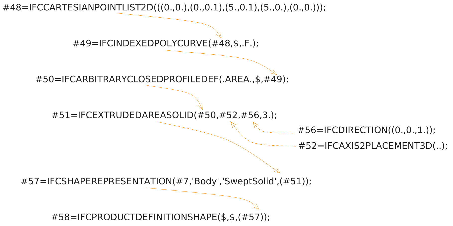
Traversing the graph from top to bottom :
Defines an ordered collection of two-dimensional Cartesian points.
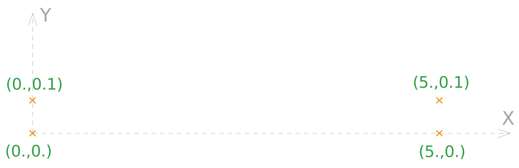
#48=IFCCARTESIANPOINTLIST2D(((0.,0.),(0.,0.1),(5.,0.1),(5.,0.),(0.,0.)));
CoordList list of the 2D points, notice that the last one refers back to the first one to close the loop. The length and width can be derived implicitly.
Creates a bounded curve by connecting the previously defined 2D Cartesian points.
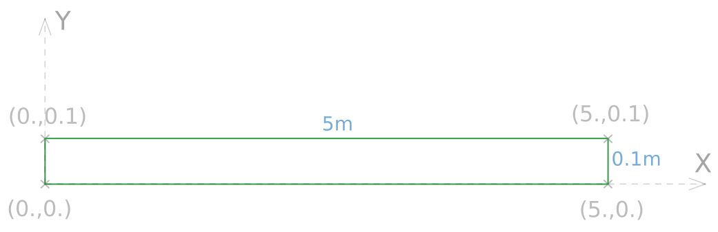
#49=IFCINDEXEDPOLYCURVE(#48,$,.F.);
Points : List of points := #48
?Segments : List of segments, unused in our example := $
?SelfIntersect : Indication of whether the curve intersects itself or not; this is for information only := .F. (False)
Defines an arbitrary two-dimensional profile for the use within the swept surface geometry.
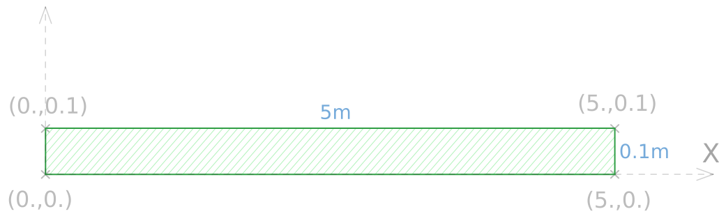
#50=IFCARBITRARYCLOSEDPROFILEDEF(.AREA.,$,#49);
ProfileType Defines the type of geometry used, from the enumeration IfcProfileTypeEnum. In our case := .AREA.
ProfileName : Human-readable name of the profile := $
OuterCurve : Bounded curve, defining the outer boundaries of the arbitrary profile := #49
Defined by sweeping a cross-section provided by a profile definition.
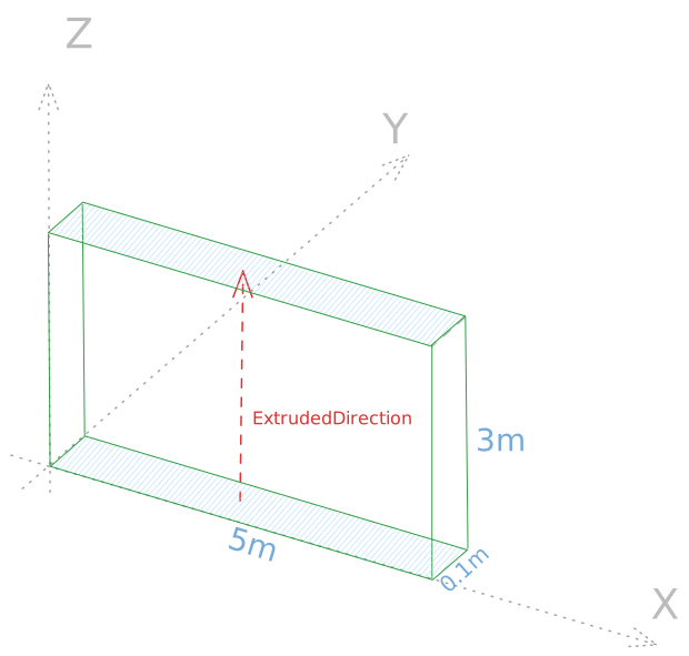
#51=IFCEXTRUDEDAREASOLID(#50,#52,#56,3.);
SweptArea : The surface defining the area to be swept := #50
Position : Position of the surface, place at the origin of the wall’s placement := #52
ExtrudedDirection : The direction in which the surface, provided by *SweptArea* is to be swept := #56 (Z axis)
Depth : The distance the surface is to be swept along the ExtrudedDirection, in our case expressing the height of our wall := 3. (in the project’s length units, i.e. m)
Defines the representation of a physical element or one of its parts, within a specific geometric representation context.
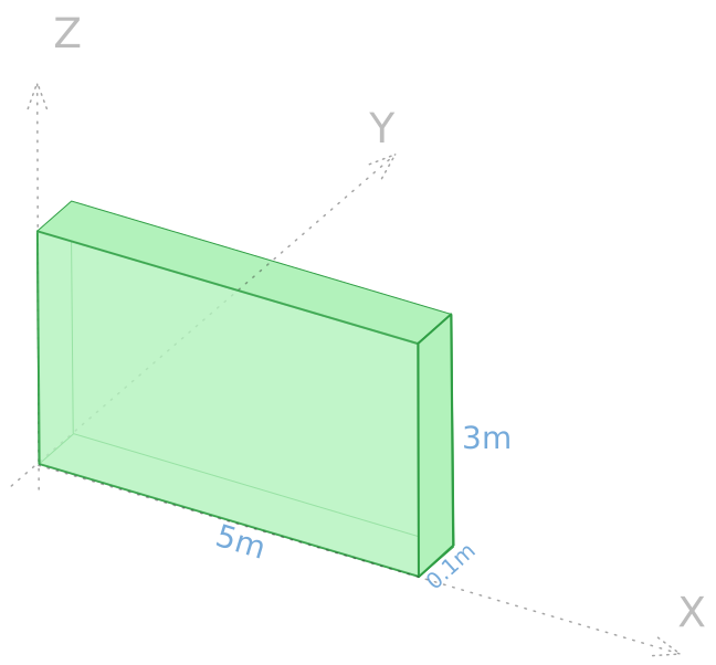
#57=IFCSHAPEREPRESENTATION(#7,'Body','SweptSolid',(#51));
ContextOfItems : The context i.e. “view” for which this representation is destined := #57 (see part 1)
RepresentationIdentifier : Identifier of the representation as used within a project, see part 1 for a detailed explanation := 'Body'
RepresentationType : The description of the type of representation := 'SweptSolid'
Items : Set of geometric representation items that are defined for this representation := #51
Defines all shape relevant information about a physical element. It allows for multiple geometric shape representations of the same product (3D, 2D, annotations …)
The resulting lines to be added are ass follows :
..../* WALL ↓ */#39=IFCWALL('0I8UD4qB9DjwVCwE644OEQ',$,'Wall',$,$,#47,#58,$,$);..../* WALL GEOMETRY*/#48=IFCCARTESIANPOINTLIST2D(((0.,0.),(0.,0.1),(5.,0.1),(5.,0.),(0.,0.)));#49=IFCINDEXEDPOLYCURVE(#48,$,.F.);#50=IFCARBITRARYCLOSEDPROFILEDEF(.AREA.,$,#49);#51=IFCEXTRUDEDAREASOLID(#50,#52,#56,3.);#52=IFCAXIS2PLACEMENT3D(#53,#54,#55);#53=IFCCARTESIANPOINT((0.,0.,0.));#54=IFCDIRECTION((0.,0.,1.));#55=IFCDIRECTION((1.,0.,0.));#56=IFCDIRECTION((0.,0.,1.));#57=IFCSHAPEREPRESENTATION(#7,'Body','SweptSolid',(#51));#58=IFCPRODUCTDEFINITIONSHAPE($,$,(#57));
To effectively assign the geometry to the wall, the attribute ?Representation should be set to #58
Thus far, we’ve successfully written an IFC model (see attached file) with a physical wall and its geometry, contained in a spatial hierarchy. In the third part of this blog series, we will be adding data (material, quantities, properties …) to the wall.